
Introduction
Fiber optic cables are the foundation of many modern high-speed networks, connecting servers, switches, data centers, cloud infrastructure, and enterprise networks with high-bandwidth optical communication. As network speeds increase from 10G and 25G to 100G and 400G Ethernet, maintaining the physical integrity of fiber connections becomes increasingly important for reliable network performance.
A fiber optic cable may appear simple from the outside, but its optical characteristics directly affect the quality of the network connection. Excessive bending, connector contamination, poor polishing, excessive insertion loss, and optical reflections can reduce signal quality and eventually cause packet loss, retransmissions, link flapping, and application performance problems.
Understanding how fiber optic cables behave helps network engineers design reliable network infrastructure, troubleshoot unexpected performance problems, and maintain consistent network visibility across high-speed Ethernet environments.
This guide explains the most important fiber optic cable concepts, including bend radius, macrobending, microbending, optical power budgets, insertion loss, return loss, fiber connectors, dispersion, connector contamination, and fiber testing.
What Are Fiber Optic Cables?
Fiber optic cables transmit information using pulses of light rather than electrical signals. A typical optical fiber consists of a central core, surrounding cladding, and protective coating.
The core carries the optical signal while the cladding helps keep light within the fiber through total internal reflection.
Fiber optic cables are widely used in:
- Enterprise networks
- Data centers
- Telecommunications
- Cloud infrastructure
- High-speed Ethernet
- Long-distance network links
- Storage networks
- Network monitoring infrastructure
- Network security infrastructure
Their ability to support high bandwidth over long distances makes fiber optics particularly important as organizations deploy higher-speed network infrastructure.
Fiber connections also provide the physical transport layer for traffic that may later be accessed by network TAPs, network packet brokers, packet capture systems, and network monitoring tools.
Why Fiber Optic Cable Condition Matters for Network Performance
Fiber problems do not always appear as an obvious physical cable failure.
A damaged or poorly installed fiber optic cable can gradually reduce optical signal quality. The network may remain operational while experiencing:
- Increased optical loss
- Higher bit error rates
- Packet retransmissions
- Packet loss
- Increased latency
- Link flapping
- Reduced application performance
This is why physical-layer problems can eventually become network-layer problems.
For example:
Damaged Fiber → Optical Loss → Bit Errors → Packet Loss → Retransmissions → Higher Latency → Application Performance Problems
Network monitoring may identify the symptoms, while fiber inspection and testing can help identify the physical cause.
Why You Should Never Bend Fiber Optic Cables
One of the most important rules when installing fiber optic cables is to respect the cable’s minimum bend radius.
When a fiber is bent too tightly, light can escape from the fiber core instead of remaining confined within it. This creates bending loss and reduces the amount of optical power reaching the receiver.
The problem occurs in two primary forms:
Macrobending
Macrobending occurs when a fiber optic cable is subjected to a large, visible bend.
Examples include:
- Routing a cable around a sharp rack edge
- Bending fiber inside a crowded patch panel
- Forcing a cable through a narrow conduit
- Kinking a patch cable during installation
- Exceeding the manufacturer’s bend-radius specification
When the bend becomes too tight, the propagation conditions inside the fiber change and some optical energy escapes from the core.
The result is increased signal attenuation.
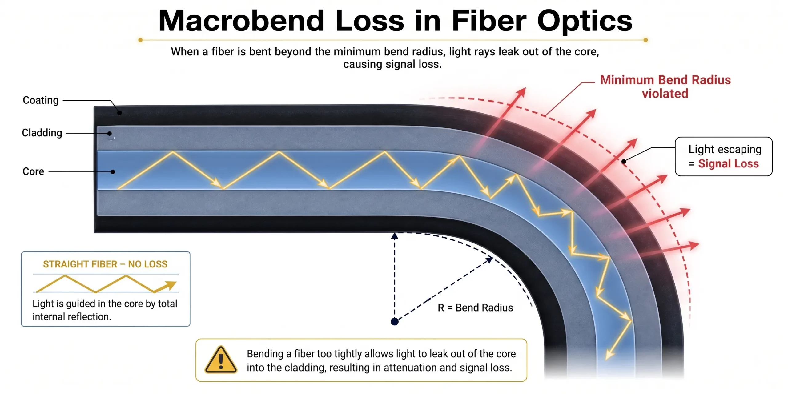
Diagram 1 : Macrobending
Microbending
Microbending is different because the deformation may not be visible.
Small distortions can occur when fiber is exposed to:
- Excessive pressure
- Over-tightened cable ties
- Improper cable trays
- Mechanical stress
- Temperature changes
- Poor cable management
These microscopic deformations can scatter optical energy and increase attenuation.
Because microbending may not be visible during a visual inspection, fiber testing becomes important when troubleshooting unexplained optical performance problems.

Diagram 2 : Microbending
How Fiber Bending Can Affect an Ethernet Network
Fiber bending is a physical-layer problem, but its consequences can propagate through the entire network.
1. Signal Attenuation
The optical signal arriving at the receiver becomes weaker.
2. Increased Bit Error Rate
The receiver has more difficulty accurately interpreting the transmitted data.
3. Packet Loss
Corrupted Ethernet frames may be discarded.
4. Retransmissions
Protocols such as TCP may retransmit missing data.
5. Increased Latency
Additional retransmissions consume bandwidth and increase communication delays.
6. Link Flapping
If the optical signal repeatedly crosses the receiver’s operating threshold, the network interface may repeatedly transition between UP and DOWN states.
This demonstrates an important troubleshooting principle:
A network performance problem does not always originate inside the network device.
The physical fiber connection itself can be the source of the problem.
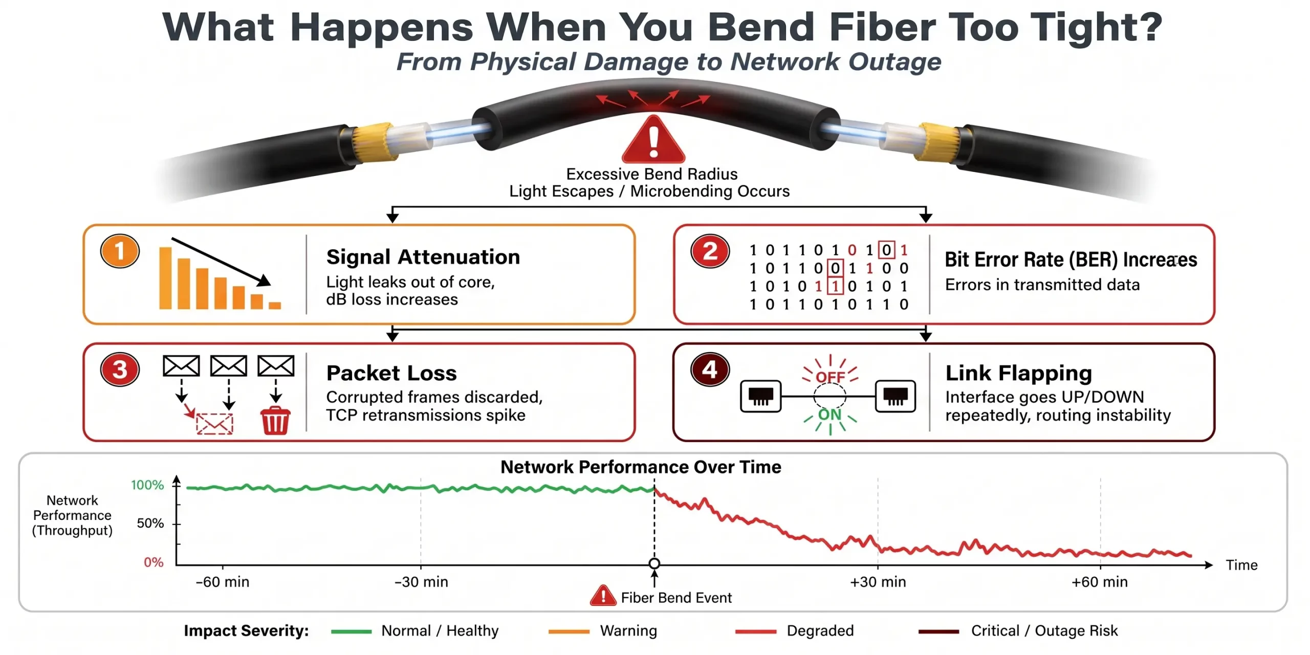
Diagram 3 : Affect of Fiber Bending on Ethernet
Understanding Fiber Optic Cable Bend Radius
The minimum bend radius specifies how tightly a fiber optic cable can safely be bent.
The exact requirement depends on the cable design and manufacturer’s specification, so engineers should always follow the cable’s documented bend radius rather than relying on a universal rule.
For many conventional cable designs, installation guidance distinguishes between:
- Dynamic bend radius during installation
- Static bend radius after installation
Bend-insensitive fiber designs such as G.657 can tolerate tighter bends than conventional fiber, but they are not immune to installation damage or optical loss.
Proper cable routing, bend-radius guides, and appropriate cable-management systems remain important in high-density network infrastructure.
Fiber Optic Cable Standards
Several ITU-T fiber recommendations are relevant when evaluating fiber characteristics.
G.652
A widely deployed conventional single-mode fiber specification.
G.657
A family of bend-insensitive single-mode fibers designed to tolerate tighter bends.
The exact performance characteristics depend on the specific fiber category and installation requirements.
For network engineers, the important consideration is to match the fiber type to the physical environment, transmission distance, optical equipment, and expected bend conditions.
Understanding Optical Power Budget
An optical link must have enough optical power at the receiver for reliable communication.
A simplified optical power budget can be expressed as:
Optical Power Budget = Transmitter Output Power − Receiver Sensitivity
The available budget must account for losses introduced by the complete optical link.
These can include:
- Fiber attenuation
- Connector insertion loss
- Splice loss
- Patch-panel connections
- Other passive components
- Engineering safety margin
If total optical loss exceeds the available power budget, the receiver may no longer be able to reliably decode the signal.
This is particularly important in high-speed Ethernet and long-distance fiber links.
Insertion Loss vs. Return Loss
Two important measurements used when evaluating fiber connections are Insertion Loss (IL) and Return Loss (RL).
What Is Insertion Loss?
Insertion loss represents the amount of optical power lost when light passes through a connection or component.
Lower insertion loss is generally better.
Sources of insertion loss can include:
- Connector misalignment
- Dirty end-faces
- Poor polishing
- Damaged connectors
- Splices
- Excessive fiber bending
What Is Return Loss?
Return loss measures the amount of optical power reflected back toward the transmitter.
Higher return loss is generally preferred because excessive reflections can negatively affect optical transmission.
Connector geometry and polish type have a significant impact on return loss.
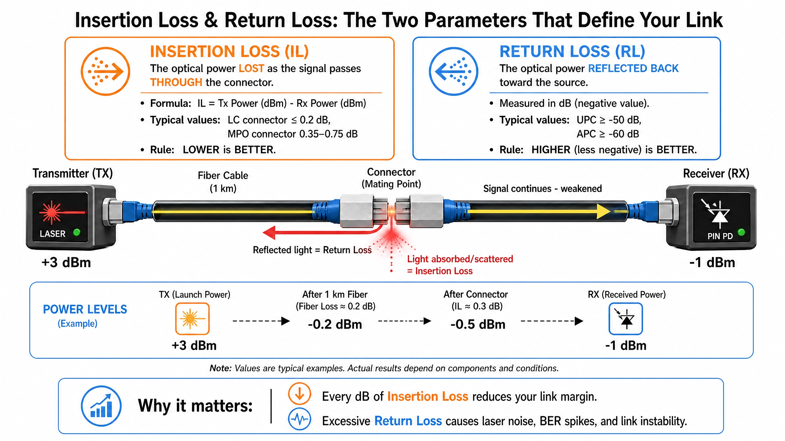
Diagram 4 : Insertion Loss vs Return Loss
Fiber Optic Connectors: LC vs. MTP/MPO
Fiber connectors provide the physical interface between optical components.
Two common connector families in modern network infrastructure are LC and MTP/MPO.
LC Connectors
LC connectors use a compact 1.25 mm ferrule and are widely used in enterprise networks and data centers.
They are commonly found in:
- Switch connections
- Server connections
- Patch panels
- 10G Ethernet
- 25G Ethernet
- Duplex optical links
Their compact form factor makes LC connectors useful where rack density is important.
MTP/MPO Connectors
MTP/MPO connectors provide high-density multi-fiber connectivity.
They are particularly important for high-speed data center architectures and parallel-optics applications.
MTP/MPO connectivity can support applications involving:
- 40G
- 100G
- 400G
- High-density spine-and-leaf architectures
As network speeds increase, high-density optical connectivity becomes increasingly important for scalable data center infrastructure.
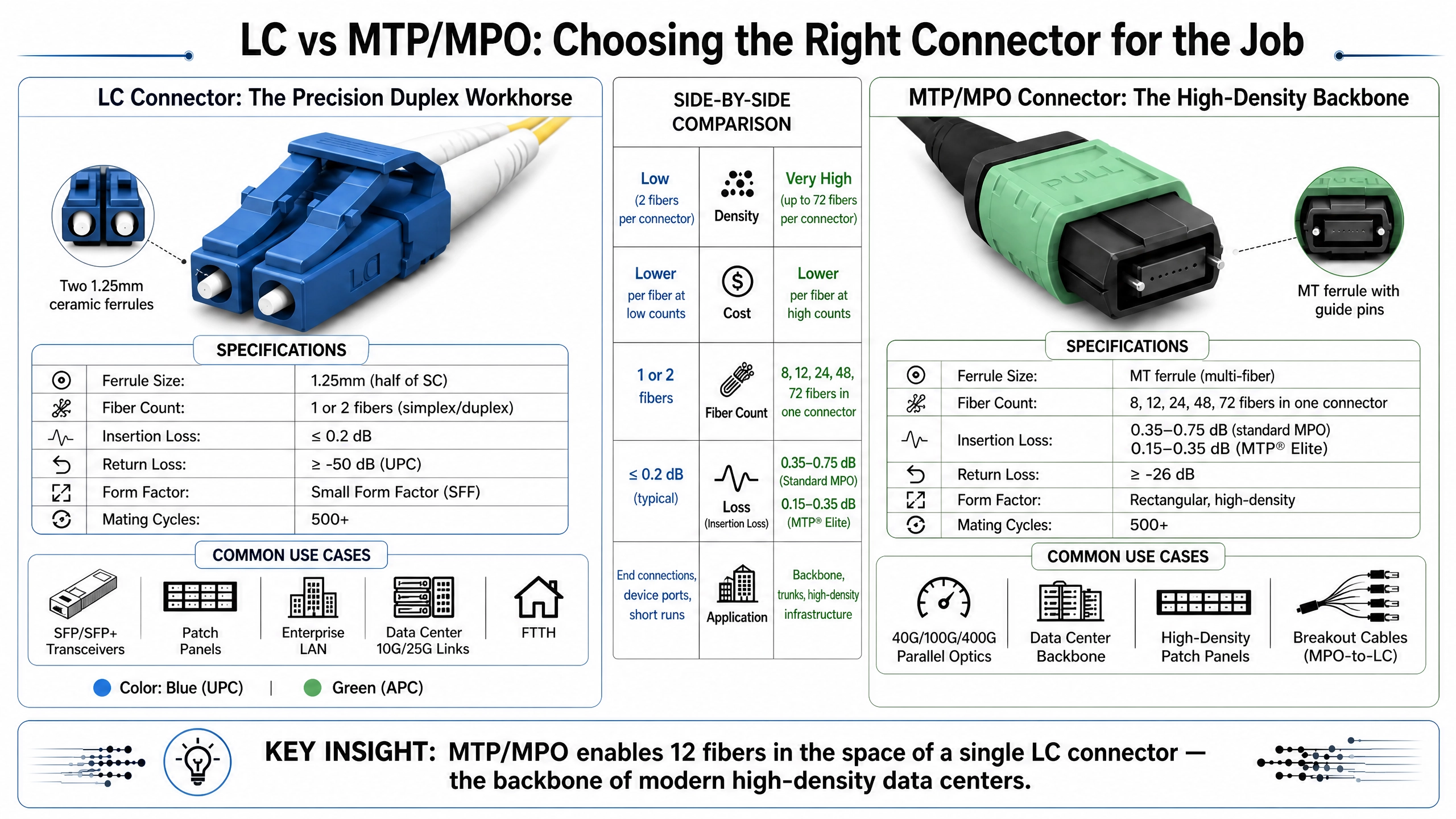
Diagram 5 : Fiber Optic Connectors
Why Fiber Connector Contamination Causes Network Problems
One of the most common causes of fiber-link degradation is connector contamination.
Fiber connector end-faces are extremely small. Dust, oil, debris, and other contaminants can interfere with the optical interface.
Contamination can cause:
- Increased insertion loss
- Increased reflections
- Higher bit error rates
- Packet errors
- Link instability
- Permanent connector damage
The problem can become worse when contaminated connectors are mated because contaminants can become embedded into the end-face.
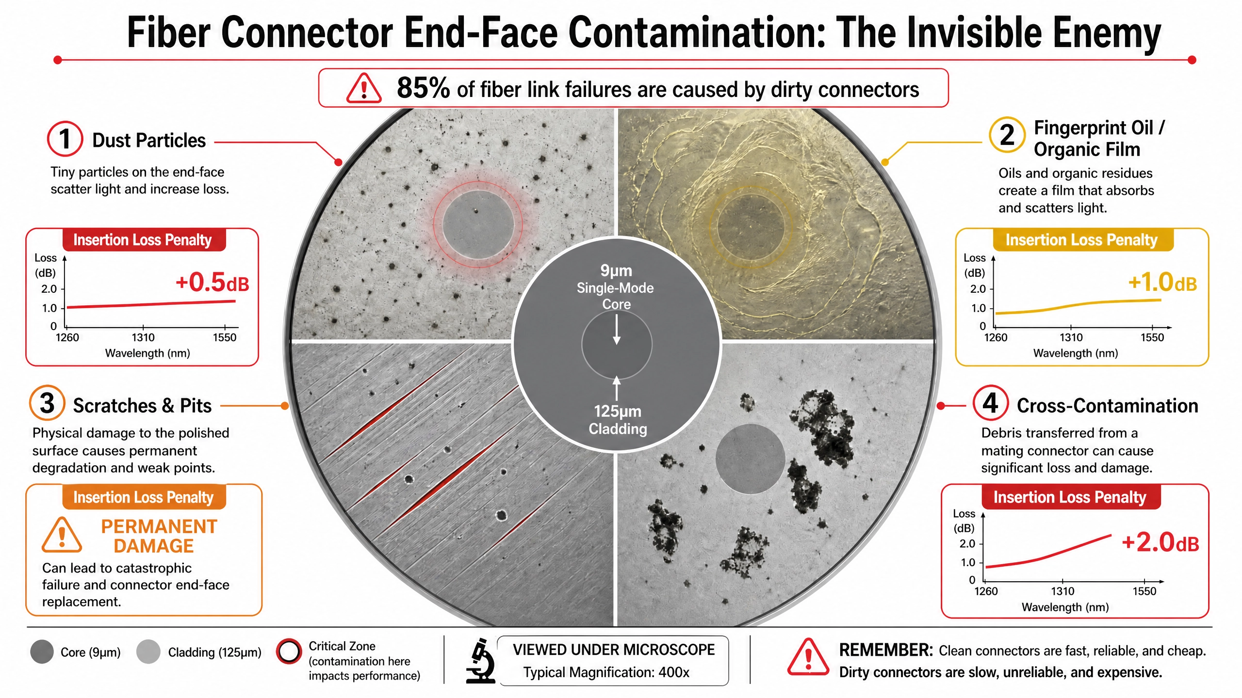
Diagram 6 : Fiber Connector Contamination Network Problem
The Fiber Inspection and Cleaning Process
A strong maintenance process follows a simple principle:
Inspect → Clean → Inspect → Connect
Never assume that a connector is clean simply because it has a dust cap.
Before connecting fiber:
- Inspect the connector end-face.
- Clean it using an appropriate fiber-cleaning method.
- Inspect it again.
- Connect it only after confirming that the end-face is clean.
The IEC 61300-3-35 standard provides guidance for inspection of fiber-optic connector end-faces.
Proper inspection and cleaning can prevent avoidable optical loss and network downtime.
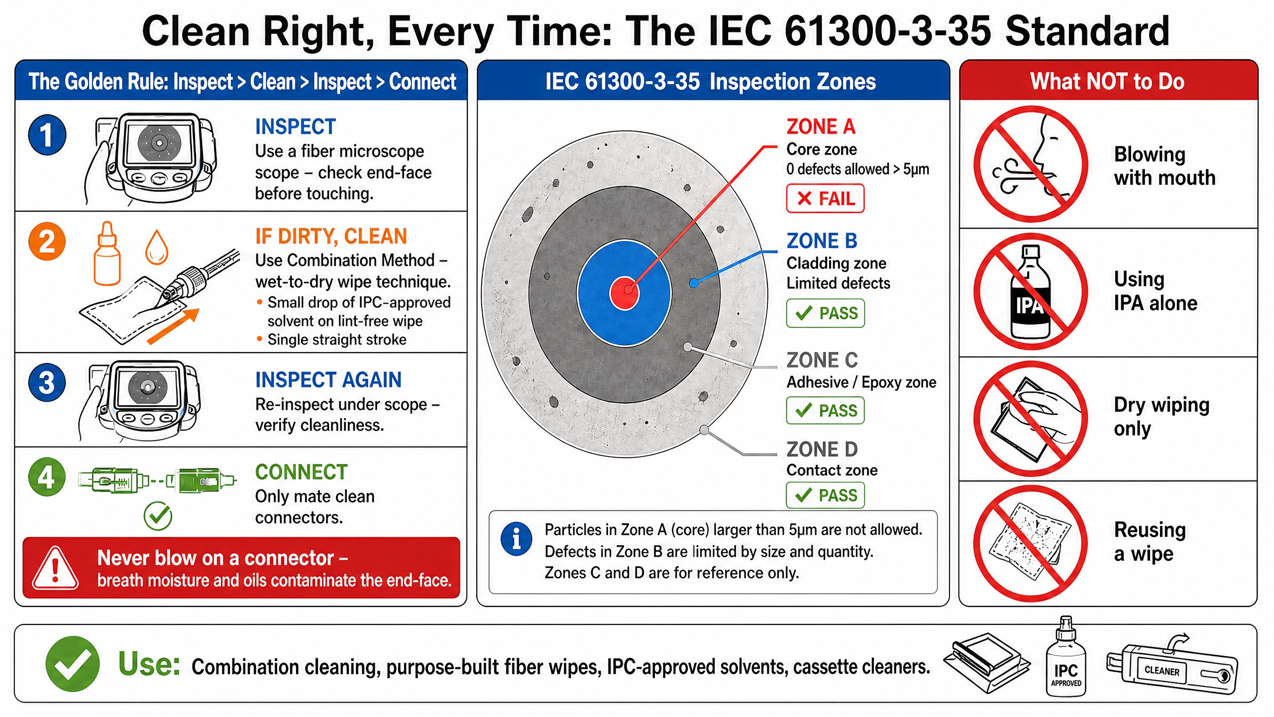
Diagram 7: Fiber Cleaning Process
Fiber Connector Polish Types
Fiber connectors can use different end-face geometries.
The most common polish types include:
- PC
- UPC
- APC
PC and UPC
Physical Contact and Ultra Physical Contact connectors use a convex end-face geometry designed to bring the fiber cores into close contact.
UPC provides a finer polish and can offer improved optical performance compared with standard PC.
APC
Angled Physical Contact connectors use an angled end-face, commonly around 8 degrees.
The angled geometry redirects reflected light away from the optical source, providing higher return-loss performance.
APC connections are commonly associated with applications where low back reflection is particularly important.
Important Compatibility Rule
Do not mate APC and UPC connectors together.
The different end-face geometries can prevent proper physical contact and cause excessive optical loss or damage.
Always verify connector type and polish before making a connection.
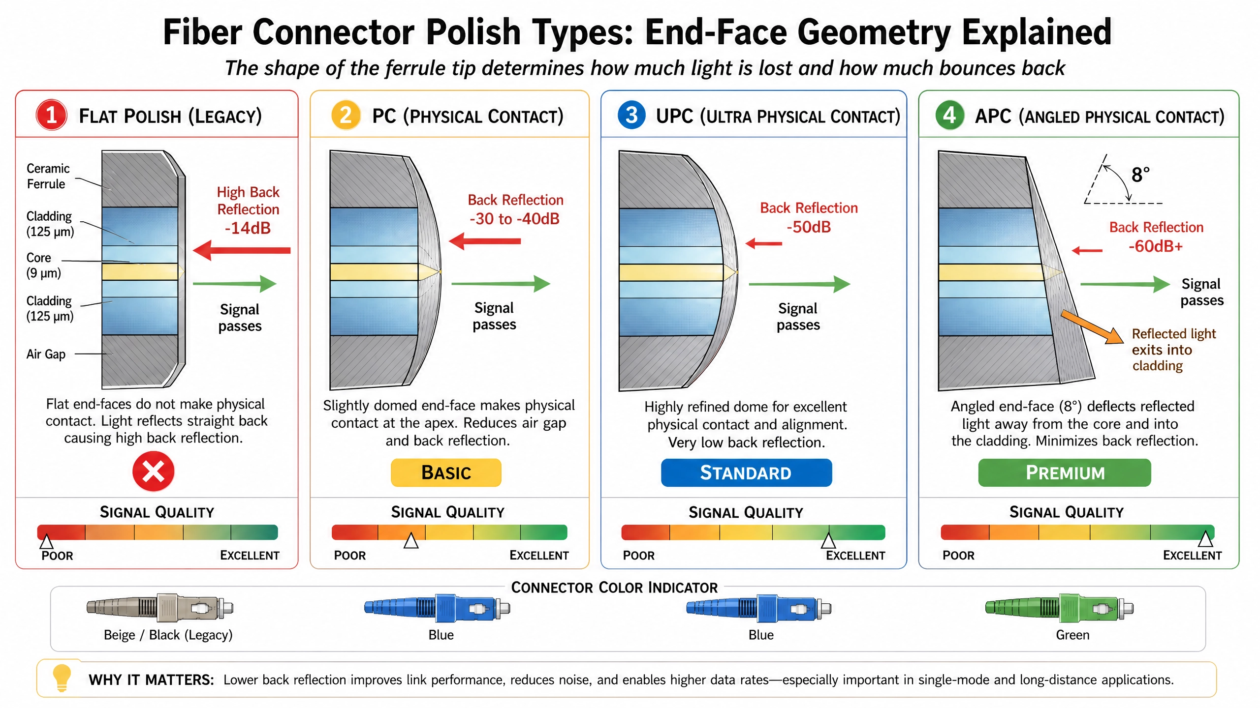
Diagram 8 : Polish Types
Fiber Dispersion and High-Speed Networks
As optical signals travel over distance, dispersion can cause the signal to spread over time.
Three important forms include:
Modal Dispersion
Modal dispersion primarily affects multimode fiber.
Different modes of light can travel different paths through the fiber and reach the receiver at different times.
Chromatic Dispersion
Chromatic dispersion occurs because different wavelengths of light can travel at slightly different velocities through the fiber.
It becomes particularly important in longer single-mode links and high-speed optical systems.
Polarization Mode Dispersion
Polarization mode dispersion results from differences in propagation speed between polarization states.
It can become an important consideration in high-speed and long-distance optical transmission.
Multimode vs. Single-Mode Fiber
The two major fiber categories used in network infrastructure are multimode fiber (MMF) and single-mode fiber (SMF).
Multimode Fiber
Common grades include:
- OM3
- OM4
- OM5
Multimode fiber is widely used for shorter-distance data center and enterprise connections.
Single-Mode Fiber
Common deployments use OS2-class fiber for longer-distance connectivity.
Single-mode fiber is commonly used for:
- Data center interconnects
- Long-distance Ethernet
- Telecommunications
- Campus networks
- Metro networks
The correct choice depends on distance, optical transceivers, bandwidth requirements, and network architecture.
Fiber Optic Cables in High-Speed Ethernet Networks
Fiber infrastructure becomes increasingly important as organizations deploy 25G, 40G, 100G, and 400G Ethernet.
At these speeds, small physical-layer problems can have significant operational consequences.
Network engineers need to consider:
- Fiber type
- Connector type
- Optical transceiver compatibility
- Insertion loss
- Return loss
- Bend radius
- Link distance
- Optical power budget
- Connector cleanliness
A reliable physical layer is essential before organizations can expect reliable network visibility, packet capture, and network monitoring at high speeds.
How Fiber Problems Affect Network Visibility
Network visibility depends on having reliable access to network traffic.
If a fiber link experiences excessive loss or intermittent connectivity, the resulting packet errors and link instability can affect the traffic that monitoring systems receive.
This can create misleading symptoms.
For example:
Fiber Problem → Packet Errors → Traffic Disruption → Monitoring Anomaly
Network engineers may initially investigate a network packet broker, monitoring platform, or packet capture system when the underlying issue is actually the physical optical link.
This is why effective network troubleshooting should consider both the physical layer and the monitoring architecture.
Fiber Optic Cables and Network TAPs
Fiber optic cables are also commonly used with network TAPs to provide passive access to network traffic.
A network TAP can copy traffic from an optical link and send that copy toward monitoring or security tools while maintaining the production traffic path.
A typical visibility architecture can look like:
Fiber Link → Network TAP → Network Packet Broker → Monitoring Tools
The Network Packet Broker can then filter, aggregate, deduplicate, and distribute the traffic to:
- Packet Capture Appliance
- Network Monitoring
- NDR
- IDS/IPS
- Security Monitoring
- Network Observability Platforms
This makes reliable fiber connectivity an important component of the overall network visibility architecture.
Fiber Testing and Troubleshooting
When a fiber link experiences unexpected performance problems, network engineers can use several testing methods to isolate the cause.
Common approaches include:
Visual Inspection
Check connectors, cable routing, bends, and physical damage.
Fiber End-Face Inspection
Identify contamination, scratches, pits, and other connector defects.
Optical Power Testing
Measure the optical power available at the receiver.
OTDR Testing
An Optical Time-Domain Reflectometer can help identify events and loss locations along a fiber link.
Packet-Level Monitoring
Once the physical link is operational, network monitoring and packet capture can help identify the resulting network behavior.
Combining physical-layer testing with network packet capture and network monitoring provides a more complete troubleshooting approach.
Best Practices for Fiber Optic Cable Management
To maintain reliable fiber infrastructure:
- Respect the manufacturer’s minimum bend radius.
- Avoid sharp bends and cable kinks.
- Use appropriate cable-management systems.
- Avoid excessive pressure from cable ties.
- Use Velcro where appropriate for cable management.
- Keep connectors capped when not in use.
- Inspect fiber end-faces before connection.
- Clean contaminated connectors correctly.
- Match APC and UPC connector types correctly.
- Verify optical power budgets.
- Test new or repaired links.
- Use OTDR testing where appropriate.
- Document fiber routes and connections.
- Monitor high-speed links for optical and network errors.
These practices reduce avoidable failures and make network troubleshooting easier.
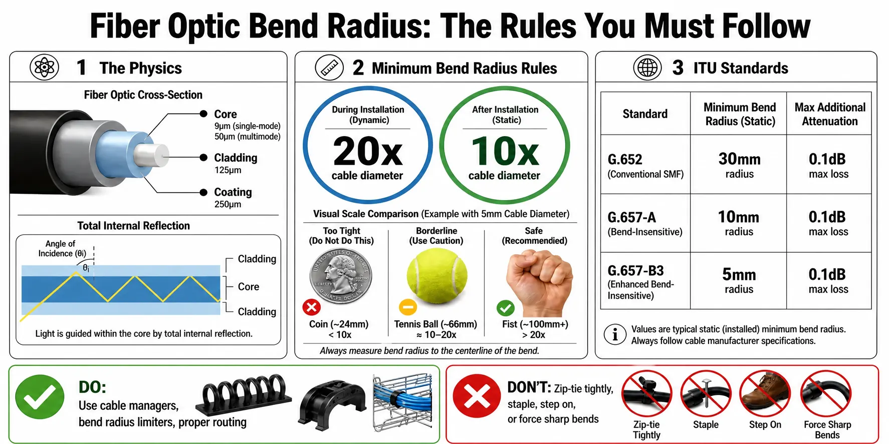
Diagram 9 : Best Practices
Fiber Optic Cable Troubleshooting Checklist
When an optical Ethernet link is unstable, investigate the problem systematically.
Physical Layer
Check:
- Cable bends
- Connector condition
- Connector cleanliness
- Cable damage
- Patch-panel routing
Optical Layer
Check:
- Transmitter power
- Receiver sensitivity
- Insertion loss
- Return loss
- Optical power budget
Network Layer
Check:
- Bit errors
- Packet loss
- Retransmissions
- Link flapping
- Interface errors
Visibility Layer
Check:
- Network TAP
- Network Packet Broker
- Packet Capture Appliance
- Monitoring tools
- Network traffic capture
This layered approach helps engineers avoid treating every network problem as a software or configuration issue.
Key Takeaways
Fiber optic cables are more than physical connections between network devices. Their condition directly affects optical signal quality, Ethernet reliability, packet transmission, and ultimately application performance.
The most important concepts to remember are:
- Never exceed the manufacturer’s bend-radius specification.
- Understand the difference between macrobending and microbending.
- Monitor insertion loss and return loss.
- Maintain sufficient optical power budget.
- Keep fiber connector end-faces clean.
- Never incorrectly mate APC and UPC connectors.
- Select the appropriate fiber type for the distance and bandwidth.
- Test optical links when troubleshooting unexplained network problems.
- Consider physical-layer problems when investigating packet loss and link instability.
- Maintain reliable fiber infrastructure for high-speed network visibility.
For modern data centers and enterprise networks, reliable fiber infrastructure provides the physical foundation on which high-speed Ethernet, network visibility, network TAPs, packet capture, Network Packet Brokers, and network observability depend.
FAQs
What is the minimum bend radius for a fiber optic cable?
The minimum bend radius depends on the cable design and manufacturer specifications. Exceeding it can cause macrobending or microbending losses and reduce optical signal quality.
What is the difference between macrobending and microbending in fiber optics?
Macrobending involves visible, large-radius bends, while microbending involves small, often invisible deformations caused by pressure, cable ties, mechanical stress, or temperature changes.
What causes insertion loss in fiber optic cables?
Insertion loss can result from connector misalignment, dirty or damaged end-faces, poor polishing, fiber bends, splices, and other passive components in the optical link.
What is the difference between insertion loss and return loss?
Insertion loss measures optical power lost as light passes through a connection, while return loss measures reflected optical power returning toward the transmitter. Lower insertion loss and higher return loss are generally preferred.
Why does fiber connector contamination cause network problems?
Dust, oil, and debris on fiber connector end-faces can increase insertion loss and reflections, potentially causing bit errors, packet loss, link instability, and degraded network performance.
Can APC and UPC fiber connectors be connected together?
No. APC and UPC connectors have different end-face geometries and should not be mated together. Doing so can cause excessive optical loss or potentially damage the connectors.
How do you troubleshoot a fiber optic network connection?
Start with physical inspection and connector end-face inspection, then check optical power, insertion loss, return loss, and bend conditions. OTDR testing can help locate faults, while packet capture and network monitoring can identify resulting network-level problems.