
Understanding Network TAPs: A Comprehensive Guide by Neox Networks
Network visibility is a cornerstone of modern IT infrastructure. At Neox Networks, we specialize in providing innovative Network TAPs (Test Access Point) solutions that ensure complete visibility into network traffic without compromising performance or security. This guide offers a detailed explanation of Network TAPs, including their architecture, types, and advantages over traditional port mirroring methods.
What Is a Network TAP?
A Network TAP (Test Access Point) is a hardware device that allows access to data flowing across a network link. It copies all network traffic, sending identical streams to monitoring and security tools for analysis. Unlike SPAN (Switched Port Analyzer) ports, TAPs provide an unaltered and continuous stream of traffic, ensuring accuracy for diagnostics, monitoring, and cybersecurity purposes. Network TAPs operate at the physical layer, ensuring complete visibility into both inbound and outbound traffic without introducing latency or packet loss. They are essential for maintaining reliable network performance, detecting anomalies, and enhancing overall data security.
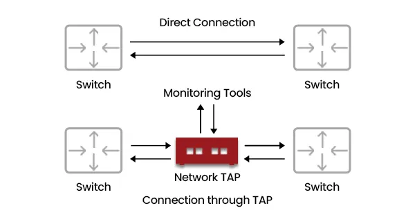
Diagram 1 : Direct vs TAP Connection
Types of Network TAPs
1. Passive Network TAPs
A passive Network TAPs requires no external power. It uses an optical splitter to divide light signals in fiber networks, providing a precise copy of the data. Passive TAPs are used for fiber connections and ensure that even during power outages, network monitoring continues uninterrupted.
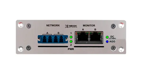
Diagram 3 : Example of NEOX PacketRaven Ports
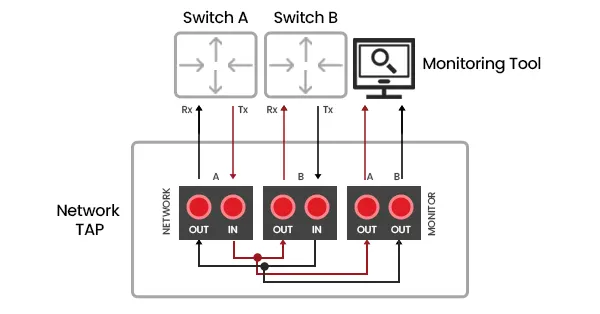
Diagram 2 : Network to Monitoring Ports Connections
Fiber TAPs and Optical Tapping
A fiber TAPs, also known as an optical TAPs, is a specialized passive device that splits a light signal into two identical paths. Optical tapping allows real-time monitoring of data transmission without impacting live traffic. At Neox Networks, we offer fiber TAPs that support single-mode and multi-mode fiber, ensuring minimal insertion loss and high accuracy.
Understanding Optical Splitters in Passive Network TAPs
Optical splitters are the core components of passive Network TAPs. They divide a single optical signal into two separate paths — one continues through the active network link, and the other is directed to the monitoring port for visibility. This technique, called optical tapping, enables complete data observation without altering or interrupting live traffic.
Types of Optical Splitters
There are two main types of optical splitters used in TAPs — Fused Biconical Taper (FBT) and Thin Film Splitters (TFS).
1. Fused Biconical Taper (FBT) Splitters: These are created by heating and stretching two optical fibers until they fuse. A portion of the light from one fiber is transferred into the other. FBT splitters are affordable and effective for short-range, lower-speed multimode applications.Because the fibers are fused and the evanescent waves of the adjacent fibers overlap, the optical energy couples, or “leaks,” from the input fiber to the adjacent fibers. The splitting ratio (e.g., 50/50, 70/30) is precisely controlled by monitoring the power output in real-time and stopping the stretching process when the desired power distribution is achieved.
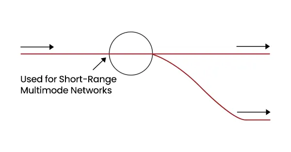
Diagram 4 : Fused Biconical Taper
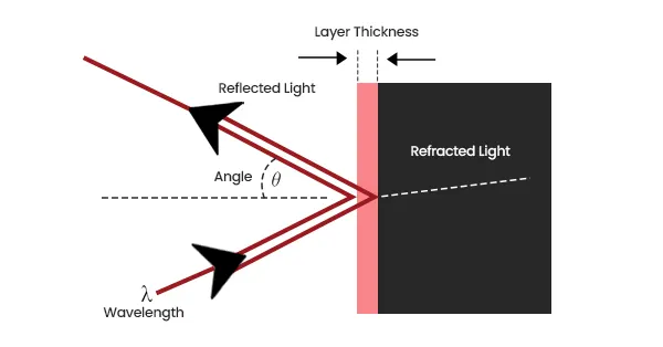
Diagram 5 : Thin Film Splitters
2. Thin Film Splitters (TFS): These use a reflective coating on a glass surface to redirect part of the light beam to the monitor port. They provide consistent light distribution and are best for high-speed networks such as 10G, 25G, 40G, 100G and 400G fiber links. A TFF is created by depositing multiple, microscopic layers of specialized dielectric materials onto a glass substrate. These layers alternate between high and low refractive indices, creating a highly specific optical coating.
Specialized 40G BiDi TAP
Thin Film technology is also an ideal choice for bidirectional TAPs links, such as 40G Cisco BiDi connections, because it enables the simultaneous reflection of multiple light wavelengths. This capability allows each wavelength—or lambda—to be separated efficiently for precise monitoring and analysis. Cisco BiDi utilizes advanced 40G technology over standard LC-based cabling, significantly reducing the costs and complexity typically associated with high-speed link deployment. This approach has become increasingly popular in modern data center environments, particularly within Cisco leaf-spine architectures, where scalability and performance are critical. Figure 5 illustrates how this innovative reflective technology functions within a highly specialized passive TAPs, ensuring optimal visibility and network efficiency.
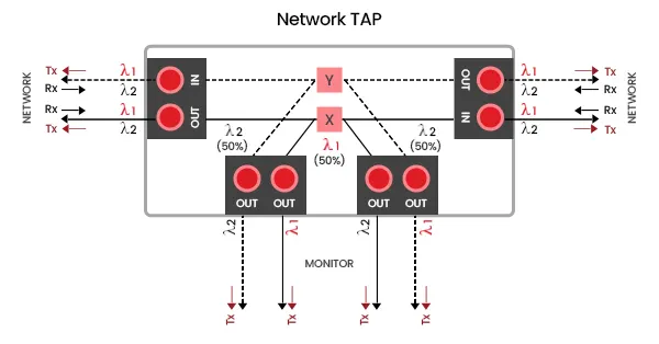
Diagram 6 : Network to Monitoring Ports Connections for BIDI
Split Ratios and Optical Power
Optical splitters operate based on split ratios, which define how much light is sent to the live network and how much goes to the monitor. Common ratios include 70/30, 60/40, and 50/50. A 70/30 splitter sends 70% of light to the network and 30% to the monitoring tools. Neox Networks typically recommends a 50/50 ratio for high-speed applications, ensuring accurate monitoring without excessive light loss.
Each optical splitter introduces an insertion loss (in decibels), which affects the power budget. Engineers must calculate total attenuation to maintain optimal signal quality. High-precision splitters minimize this loss, ensuring reliability even under high data throughput conditions.
| Multimode Passive TAPs | |||
|---|---|---|---|
| Split ratio | 50/50 | 60/40 | 70/30 |
| Max network loss | 3.9dB | 3.15dB | 2.2dB |
| Max monitor loss | 3.9dB | 5.15dB | 6.2dB |
| Singlemode Passive TAPs | |||
| Split ratio | 50/50 | 60/40 | 70/30 |
| Max network loss | 3.7dB | 3.05dB | 2.0dB |
| Max monitor loss | 3.7dB | 4.95dB | 6.1dB |
Table 1 : Multimode and Singlemode Fiber Split Ratios
Optical Types
1. Multimode
2. Singlemode
However, because light in multimode fiber travels along multiple paths, it can scatter and arrive at slightly different times. This modal dispersion causes signal distortion and increased attenuation, which limits the effective transmission distance—typically to a few hundred meters, depending on the fiber type. For that reason, 62.5μm multimode cabling is generally recommended only for 1G speeds or lower.
In contrast, singlemode fiber uses a much smaller core to transmit light in a single path, supporting higher bandwidth and longer distances. This precision requires laser-based transmitters instead of LEDs, such as VCSELs (Vertical-Cavity Surface-Emitting Lasers) for short-to-medium distances and Fabry-Perot or DFB lasers for extended reaches up to 40km or more. Figure 8 illustrates the most common types of fiber cables used for various transmission requirements.
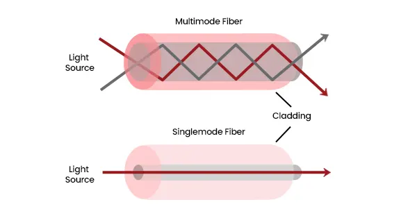
Diagram 7 : Multimode vs Singlemode Fiber
| Cable Type | Diameter (µm) | Color | Connector | Typical Usage | |
|---|---|---|---|---|---|
| OM1 | Multimode | 62.5/125 | Orange | LC/SC | FE/1G/10G |
| OM2 | Multimode | 50/125 | Orange | LC/SC | FE/1G/10G |
| OM3 | Multimode(Laser Optimized) | 50/125 | Aqua | LC/MPO | 10G/40G/100G |
| OM4 | Multimode(Laser Optimized) | 50/125 | Aqua | LC/MPO | 10G/40G/100G |
| OS1/OS2 | Singlemode | 9/125 | Yellow | LC/SC | 10G/40G/100G/400G |
| Cat 5e/Cat 6 | Copper/twisted pair | N/A | Various | RJ45 | FE/1G |
| Cat 6A | Copper/twisted pair | N/A | Various | RJ45 | 10G |
Table 2 : Cable Types
The chart represents a simplified optical link between two endpoints—one equipped with a transmitter and the other with a receiver. The link includes two connectors, one at each end, and may experience minor losses along the way.
To estimate overall link performance, the following formulas can be used:
- Power Budget
The total optical power available for transmission.
Formula: Power Budget = Transmitter Output – Receiver Sensitivity = t – r - Cable Attenuation
The gradual reduction in optical signal strength caused by absorption and scattering within the fiber.
Formula: Cable Attenuation = x – y - Connection Loss
The optical power loss introduced by the connectors and terminations used in the link.
Formula: Connection Loss = (t – x) + (y – z) - Total Cable Plant Loss
The combined loss from both the fiber and the connectors in the system.
Formula: Total Loss = (t – x) + (x – y) + (y – z) - Power Margin
The amount of extra optical power available beyond what’s required for reliable communication.
Formula: Power Margin = Power Budget – Total Cable Plant Loss - Minimum transmitter launch = −9.0 dBm.
- Receiver sensitivity = −17.0 dBm.
- Power budget = (t) − (r) = −9.0 − (−17.0) = 8.0 dB.
- Cable attenuation (10 m) = 3.5 dB/km × 0.01 km = 0.035 dB.
- Connector loss = 0.30 dB/connector × 2 connectors = 0.60 dB.
- Total cable plant loss = 0.035 + 0.60 = 0.635 dB.
- Power margin = 8.0 − 0.635 = 7.365 dB → round to ≈ 7.37 dB.
with typical modern 1G-SX SFP specs and typical LC connector loss, a 10 m OM2 run leaves ~7.37 dB of margin — noticeably larger than the ~6.47 dB from the strict IEEE worst-case example.
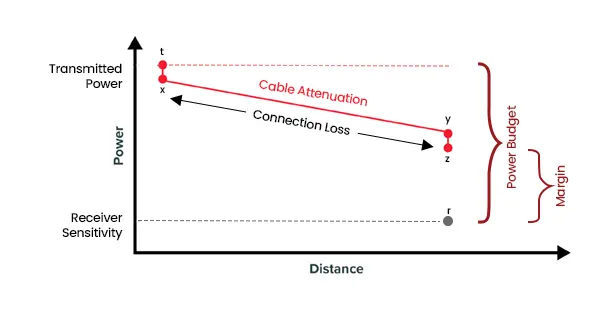
Diagram 8 : Connector Loss Chart


Diagram 9 : NEOX PacketRaven Portable 400G MM Fiber TAP (Passive TAPs)
2. Active Network TAPs
Active Network TAPs differ from passive TAPs in that they require their own power source to regenerate data signals. Unlike a passive Ethernet TAPs, which relies solely on optical splitting, an active Network TAPs amplifies and retransmits packets to both the network and monitoring tools. Because there’s no need to consider a split ratio, the active TAPs device sends a full-strength signal to each destination. While this might seem like an advantage, passive Network TAPs are generally preferred for their reliability. During a power outage, an active TAPs becomes a potential point of failure because it cannot regenerate the signal, whereas a passive TAPs—which doesn’t depend on power—continues to pass traffic seamlessly, maintaining uninterrupted network visibility. So, when are active Network TAPs the better choice? These devices are typically deployed in scenarios where passive TAPs are not ideal, such as:
- Environments with very low light levels where optical splitters are ineffective — regeneration ensures signal strength.
- Copper-based infrastructures where electrical transmission replaces photonic light.
- Signal conversion setups — for example, converting 10G SR to 10G LR links.
- SFP-based or TwinAX cabling environments where physical link breaks are not possible.
When properly understood, active Network TAPs provide exceptional visibility in complex or low-light systems. Many modern Network TAPs devices now include battery backup or failover capabilities to prevent link disruption during power loss. In such cases, electromagnetic relays automatically close the circuit, allowing live network traffic to continue flowing even if the monitoring stream pauses.


Diagram 10 : NEOX PacketRaven Hybrid SM Network TAP (Active TAPs)
FAQs
What is a Network TAP?
A Network TAP is a device that duplicates live network traffic for monitoring and analysis.
What is a Passive Ethernet TAP?
A Passive Ethernet TAP uses optical splitters to copy traffic without needing power.
What is the Difference Between Network TAP and Port Mirroring?
A TAP is hardware-based with no packet loss; SPAN is software-based and may drop data under load.
What is Optical Tapping?
Optical tapping refers to splitting light signals in fiber optic cables to monitor data traffic.
What are Aggregation TAPs for Data Centers?
They merge multiple TAP feeds into one stream for centralized monitoring and analytics.
What is a Passive LAN TAP?
A device for monitoring LAN segments passively without affecting network performance.